

Key Takeaways
SDRs enable rapid adaptation through software-defined waveforms, frequencies, and protocols.
While SDRs provide flexibility, RF front-end components such as filters, amplifiers, mixers, and switches ultimately determine sensitivity, bandwidth, dynamic range, and overall system performance. Hybrid SDR architecture combines software flexibility with RF hardware to support demanding EW, SIGINT, and Counter-UAS missions.
RFMW offers the RF components and technical expertise needed to optimize the SDR signal chain from antenna to digital backend.
Demand for More Flexible Radio Architectures
The era of single-band, fixed function radio systems is coming to an end. In demanding applications such as electronic warfare (EW), wideband spectrum surveillance, and multi-mode communications, traditional radio systems struggle to keep pace with evolving waveforms, frequencies, and mission requirements. As a result, software defined radios (SDRs) architectures have become an important part of modern system design.
What was once an experimental platform for waveform swapping has become a foundational technology for mission-critical signal acquisition, processing, and communications across defense and aerospace. With the flexibility to support multiple missions, communication standards, and operational requirements, SDR-based architectures have become a cornerstone of remote command-and-control systems, including civilian and military drones. Their ability to adapt through software enables longer system lifecycles, reduced upgrade costs, and the rapid deployment of new capabilities.
Software Defined Radios Explained
Not all SDRs are created equal. Originally developed in the 1990s, software defined radio was increasingly adopted in the early 2000s when teams began exploring frequency, modulation schemes, and protocol flexibility in radio systems. Unlike traditional radio systems, SDRs can be reconfigured to support different frequencies, waveforms, and communication protocols without requiring hardware changes.
An SDR consists of two primary elements: the RF front end and the digital processing backend. The RF front end handles signal transmission and reception, tuning across a wide frequency range, while the digital backend performs functions such as modulation, demodulation, and waveform processing.
Software Defined Radio Applications
While SDRs are used across industries ranging from test and measurement to satellite communications, their adaptability makes them particularly valuable in EW, SIGINT, and Counter-UAS applications.
Electronic Warfare (EW)
SDRs are well suited for a wide range of EW missions, including electronic attack (EA) and electronic protection (EP). Combining flexible transmit capabilities with wide instantaneous bandwidths, SDR-based systems can generate highly targeted signals designed to disrupt, deny, degrade, or deceive adversary electronic systems.
Their adaptability allows operators to address specific threats and operating environments without modifying hardware. In electronic attack applications, SDRs can also support electronic deception techniques by transmitting carefully crafted signals that mimic legitimate communications, creating confusion and reducing the effectiveness of enemy systems.
Signals Intelligence (SIGINT)
SIGINT systems must detect, monitor, and process a wide range of communications and radar signals across the spectrum. SDR architectures support flexible signal collection and waveform processing. As the US Army improves their tactical communications network, SDRs enable new capabilities and security enhancements to be deployed without replacing existing hardware. By supporting multiple waveforms on a common platform, SDRs provide warfighters with reliable access to voice, data, imagery, and video across diverse operational environments.
Counter-UAS
Counter-drone operations demand technologies that can adapt to dynamic electromagnetic environments and evolving drone communication strategies. With support for multiple communication links, evolving protocols, regional frequency requirements, and changing bandwidth demands, SDRs are increasingly being integrated into modern drone architectures.
Building Wideband SDRs: The Challenge of Receiving Everything from HF to Ka-Band
While SDRs provide tremendous flexibility, achieving this performance across increasingly wide frequency ranges and bandwidths presents significant engineering challenges. As SDRs are pushed into microwave frequencies and contested electromagnetic environments, RF front-end performance becomes increasingly important.
The ability to support multiple waveforms, frequency bands, and mission requirements without physical component replacement creates an agile and versatile approach for wide-ranging applications, including military communications, EW, signal intelligence (SIGINT), and counter-UAS.
Today’s high-performance SDR platforms are increasingly capable of tuning from HF through microwave frequencies and, in advanced implementations, can support instantaneous bandwidths measured in gigahertz. While much of the signal processing occurs in the digital domain, each radio chain still relies on RF front-end circuitry for amplification, filtering, and frequency conversion before signals reach high-speed ADCs and DACs. Behind these converters, onboard FPGAs execute DSP functions such as filtering, modulation, demodulation, up conversion, and down conversion, while supporting additional IP cores that allow the system to be tailored to specific mission requirements. This combination of software flexibility and RF hardware performance is what enables SDRs to operate effectively in the most contested RF environments.
Direct Sampling SDRs: Moving the ADC Closer to the Antenna
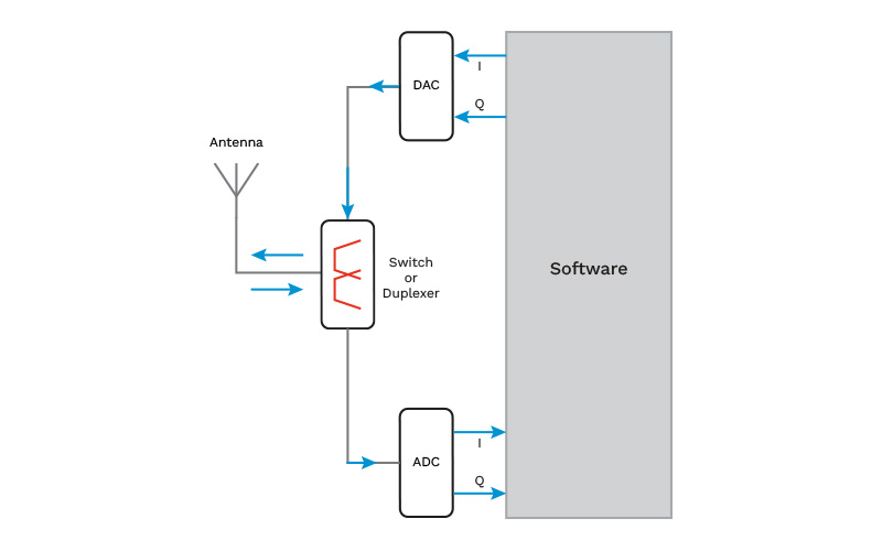
One type of SDR architecture is direct sampling, where designers push the digitizer as close to the antenna as possible. The goal is to reduce the amount of analog hardware in the signal chain and move more signal manipulation into the digital processing domain. In its purest form, the signal travels directly from the antenna, through minimal RF conditioning, and into the SDR’s high-speed converter, allowing waveform generation, modulation, filtering, and other signal processing functions to be handled primarily through software.
The appeal of this approach is clear: a simpler signal chain, maximum flexibility, and reduced dependence on dedicated analog circuitry. By performing more functions digitally, SDRs can adapt to changing waveforms, frequencies, and communication requirements without hardware modifications.
However, direct sampling is not practical for every application. ADCs and digital processors are ultimately limited by their clock speeds and operating frequencies. While they can effectively process lower-frequency signals, directly digitizing very high-frequency microwave and millimeter-wave signals remains challenging due to converter performance, power consumption, and bandwidth constraints. As operating frequencies, bandwidth requirements, and system complexity increase, additional RF solutions become necessary.
Why Hybrid SDR Architectures Continue to Dominate Defense Systems
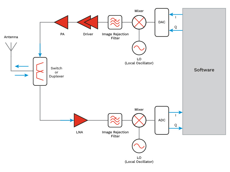
In high frequency applications such as EW, SIGINT, and C-UAS, moving directly from the antenna to the digitizer is often not enough to meet performance requirements. As operating frequencies increase and RF environments become more congested, signals must be properly conditioned before they can be accurately digitized and processed.
Hybrid SDR architectures address this challenge by combining software-defined processing with RF front-end hardware, including amplifiers, filters, and frequency-conversion stages. This approach delivers:
- Improved high-frequency performance
- Greater dynamic range
- Better interference and blocker rejection
- Reduced burden on the ADC and digital processing chain
As a result, many mission-critical SDR systems rely on hybrid architectures to balance software flexibility with the RF performance required in demanding operational environments.
Why Advanced RF Front-Ends Matter in SDR Architectures
While SDRs move many radio functions into software, overall system performance is still heavily dependent on the RF front end. Regardless of whether an SDR uses direct sampling or hybrid architecture, the quality of the signal entering the digital domain ultimately determines how well a system performs.
Simply put, software cannot fix a poor signal. Before a signal reaches the ADC, it must often be amplified, filtered, conditioned, and, in many cases, frequency converted to ensure sufficient sensitivity, dynamic range, and signal integrity. As a result, advanced RF front-end hardware remains a critical component of every high-performance SDR.
Key RF front-end functions in SDR-based architectures include:
- Low-noise amplification (LNA)
- Filtering and interference rejection
- Gain control
- RF switching
- Frequency conversion
- Signal conditioning
How RFMW Supports the Future SDR Architectures
Rather than replacing RF hardware, SDRs increase the need for well-designed RF front ends. As SDR architecture continues to push toward wider bandwidths, higher frequencies, embedded AI/ML, and RF-to-bits processing, the quality of the RF signal chain becomes more critical than ever.
The next generation of SDRs is evolving beyond communications platforms into intelligent sensing systems capable of detecting, classifying, and responding to signals in real time. Emerging architectures increasingly integrate machine learning inference engines, hardware acceleration, and edge processing capabilities directly within the radio, enabling faster decision-making, reduced latency, and greater spectrum awareness in mission-critical environments.
As a leading global distributor of RF and microwave solutions, RFMW helps engineers bridge the gap between software-defined flexibility and real-world RF performance. Our portfolio includes the critical building blocks needed to optimize SDR architectures across the entire signal chain:
SDR Core Building Blocks
SDRs rely on highly integrated RF receiver and analog front-end devices that bridge the gap between the antenna and digital processing domain. These devices perform critical functions such as signal conditioning, filtering, gain control, and frequency conversion, enabling flexible SDR architectures for communications, EW, SIGINT, and Counter-UAS applications.
CMX994EF | CMX993W | CMX983 |
· Direct Conversion Rx · RF/IF Range: 0.1-1.0 GHz · I/Q BW: >1 MHz · Vcc: 3.0 – 3.6 V · Size: 6 x 6 mm | · Quadrature Modulator · Freq: 0.3-1.0 GHz · I/Q BW: 10 MHz · Vcc: 3.0 – 3.6 V · Size: 7 x 7 mm | · Analog Front End · Tx Channel: Two 14-bit Σ-Δ A/D Converters · Rx Channel: Two 16-bit Σ-Δ A/D Converters · Vcc: 3.3 V & 1.8 V · Size: 9 x 9 mm |
Power Amplifiers
Power amplifiers increase transmit signal strength, enabling SDR platforms to support long-range communications, electronic attack, jamming, radar, and spectrum-denial operations. Wideband power amplifiers help SDR systems maintain flexibility across multiple frequency bands and mission profiles.
QPA2962 | TGA2963-CP | 1191 | MMA-121633-M5 |
· Freq: 2-20 GHz · Gain: 19 dB · Psat: 10 W · Supply: 22 Vdc | · Freq: 6-18 GHz · Gain: 26 dB · Psat: 20 W · Supply: 20 Vdc | · Freq: 2.5-6.0 GHz · Gain: 60 dB · Psat: 100 W · Supply: 28 Vdc | · Freq: 12.5-15.5 GHz · Gain: 23.5 dB · Psat: 2 W · Supply: 6 Vdc |
Low Noise Amplifiers (LNAs)
LNAs strengthen weak incoming RF signals while adding minimal noise. They are critical in SDR receivers used for EW, SIGINT, radar, and spectrum-surveillance applications where detecting low-level signals can determine mission success.
GRF2013 | AMM-9861PSM | AMM-9852PSM | QPL9547 | CMD328K3 |
· Freq: 0.01-9 GHz · Gain: 18.5 dB · P1dB: 22.5 dBm · Noise Figure: 1.9 dB · Size: 1.5 x 1.5 mm | · Freq: 3-30 GHz · Gain: 11.7 dB · P1dB: 12.4 dBm · Noise Figure: 2.5 dB · Size: 3 x 3 mm | · Freq: DC-20 GHz · Gain: 17.5 dB · P1dB: 20 dBm · Noise Figure: 1.8 dB · Size: 3 x 3 mm | · Freq: 0.1-6 GHz · Gain: 19.3 dB · P1dB: 22.7 dBm · Noise Figure: 0.3 dB · Size: 2 x 2 mm | · Freq: 6-18 GHz · Gain: 27 dB · P1dB: 12 dBm · Noise Figure: 1.4 dB · Size: 3 x 3 mm |
Gain Block & Driver Amplifiers
Gain blocks and driver amplifiers provide controlled signal amplification throughout the SDR signal chain. They help maintain signal integrity, improve dynamic range, and provide the drive levels required for mixers, converters, and high-power amplifier stages.
GRF5511 | CMD240P4 | ADM-11122PSM | MMA-012030-M4 |
· Freq: 0.4-8 GHz · Gain: 20.1 dB · P1dB: 26.1 dBm · OIP3: 39.6 dBm · Size: 3 x 3 mm | · Freq: DC-22 GHz · Gain: 15 dB · P1dB: 19 dBm · OIP3: 28 dBm · Size: 4 x 4 mm | · Freq: 2-20 GHz · Gain: 19 dB · P1dB: 13.7 dBm · OIP3: 26dBm · Size: 4 x 4 mm | · Freq: 0.1-20 GHz · Gain: 12.5 dB · P1dB: 27 dBm · OIP3: 37 dBm · Size: 4 x 4 mm |
Directional Couplers
Directional couplers sample RF signals without significantly impacting the primary signal path. They are commonly used in SDR systems for power monitoring, built-in test, calibration, feedback control, and signal measurement functions.
MC16-0222SM | FPC07237 | X4C70J1-20G | IPP-8000 |
· Freq: 2-22 GHz · Coupling: 16 dB · Directivity: 23 dB · Power Handling: 30W · Size: 4 x 4 mm | · Freq: 2-18 GHz · Coupling: 20 dB · Directivity: 10 dB · Power Handling: 10W · Size: 12.7 x 3.8 mm | · Freq: 5.7-9.2 GHz · Coupling: 20 dB · Directivity: 18 dB · Power Handling: 10W · Size: 2 x 1.3 mm | · Freq: 2-6 GHz · Coupling: 10 dB · Directivity: 18 dB · Power Handling: 100W · Size: 14.2 x 5.1 mm |
Hybrid Couplers
Hybrid couplers split and combine RF signals with precise phase and amplitude control. In SDR architectures they support balanced amplifier designs, power combining, beamforming, and signal-distribution networks used in advanced communications, EW, and radar systems.
PSC18H17S | FPC07237 | IPP-7153 | MQH-0919CSP3 |
· Freq: 2-18 GHz · Amp Bal: ±1.1 dB · Phase Bal: ±1.1° · Power: 20W · Size: 28.8 x 7 mm | · Freq: 6-18 GHz · Amp Bal: ±1 dB · Phase Bal: ±3° · Power: 50W · Size: 8.9 x 6.4 mm | · Freq: 6-12 GHz · Amp Bal: ±0.7 dB · Phase Bal: ±6° · Power: 100W · Size: 6.4 x 5.1 mm | · Freq: 9-19 GHz · Amp Bal: ±0.5 dB · Phase Bal: ±0.4° · Power: 30W · Size: 3.5 x 3.5 mm |
Filters
RF filters remove unwanted signals, noise, and interference before they reach the receiver. In SDR architectures, filters improve signal integrity, increase sensitivity, and help prevent strong out-of-band signals from degrading system performance in congested spectrum environments.
MFBT-00003PSM | 6PFX-15000/R6000-M | QPB1033 | TA1426A |
· Type: Tunable Bandpass · Center Freq: 19 GHz · Bandwidth: 22 GHz · Return Loss: 10 dB · Size: 4 x 4 mm | · Type: Bandpass · Center Freq: 15 GHz · Bandwidth: 6 GHz · Return Loss: 15 dB · Size: 6.1 x 2.7 mm | · Type: Switched-Filter Bank · Center Freq: 3 GHz · Bandwidth: 0.1 GHz · Return Loss: – dB · Size: 6 x 6 mm | · Type: Bandpass · Center Freq: 2.595 GHz · Bandwidth: 0.1 GHz · Return Loss: 14 dB · Size: 1.4 x 1.1 mm |
There are also many custom filter options, such as the Knowles custom switched filter bank series.
Limiters
Limiters protect sensitive SDR receiver components from high-power RF signals, whether from nearby transmitters, intentional jamming, or unexpected signal surges. By preventing overload and damage, they help preserve receiver performance and reliability in contested electromagnetic environments.
TGL2208-SM | HLM-100001PSM | A0101-08G-18G-P4-SMAFF | A0101-02G-08G-P0 |
· Freq: 2-20 GHz · Insertion Loss: 1 dB · Return Loss: 12 dB · CW Input Power: 5W | · Freq: DC-20 GHz · Insertion Loss: 0.9 dB · Return Loss: 22 dB · CW Input Power: 10W | · Freq: 8.4-18 GHz · Insertion Loss: 3 dB · Return Loss: 13.5 dB · CW Input Power: 10W · Frequency selective limiting | · Freq: 2-8 GHz · Insertion Loss: 2 dB · Return Loss: 12.5 dB · CW Input Power: 10W · Frequency selective limiting |
Switches
RF switches route signals between antennas, frequency bands, transmit chains, and receive paths. They enable SDR platforms to support multiple operating modes and frequency bands while maximizing flexibility, coverage, and system efficiency.
PE42520 | QPC6324 | FW2001 |
· Type: SPDT · Freq: 0.0001-13 GHz · Insertion Loss: 0.6 dB · Isolation: 90 dB · Power Handling: 4 W · Size: 3 x 3 mm | · Type: SPDT · Freq: 0.005-6 GHz · Insertion Loss: 0.9 dB · Isolation: 62dB · Power Handling: 5 W · Size: 4 x 4 mm | · Type: SPDT · Freq: 0.03-12 GHz · Insertion Loss: 0.95 dB · Isolation: 31 dB · Power Handling: 10 W · Size: 3 x 3 mm |
Mixers
Mixers perform frequency translation, converting RF signals to frequencies that can be processed more efficiently by converters and digital signal processing hardware. They enable SDRs to operate across wider frequency ranges while maintaining receiver performance.
T3-12LCQG-1 | T3-20GLCTG-1 | MMIQ-0205HSM-2 | CMD183C4 |
· RF/LO Freq: 0.01-12 GHz · IF Freq: 0.001-4 GHz · Conversion Loss: 7.5 dB · Input IP3: 30 dBm · Size: 10.16 x 8.13 mm | · RF/LO Freq: 0.01-20 GHz · IF Freq: 0.001-10 GHz · Conversion Loss: 7.5 dB · Input IP3: 27 dBm · Size: 8.13 x 8.13 mm | · RF/LO Freq: 1.75-5 GHz · IF Freq: 0-2 GHz · Conversion Loss: 8 dB · Image Rej: 33 dBc · Size: 5 x 5 mm | · RF/LO Freq: 7.5-13 GHz · IF Freq: DC-4.5 GHz · Conversion Loss: 5.5 dB · Image Rej: 26 dBc · Size: 4 x 4 mm |
Attenuators
Attenuators precisely control signal levels throughout the SDR signal chain. They improve dynamic range, prevent receiver overload, and help maintain optimal operating conditions in environments containing both very strong and very weak signals.
PE43704 | QPC6713 | QPC1008 | ATN10-0040PSM |
· Digital Step · Freq: 0.0001-8 GHz · Insertion Loss: 1.7 dB · Atten Range: 31.75 dB · Size: 5 x 5 mm | · Digital Step · Freq: 0.0001-8 GHz · Insertion Loss: 1.7 dB · Atten Range: 31.75 dB · Size: 3 x 3 mm | · Digital Step · Freq: DC-20 GHz · Insertion Loss: 5 dB · Atten Range: 31 dB · Size: 3.9 x 3.9 mm | · Fixed · Freq: DC-40 GHz · Insertion Loss: 10 dB · Flatness; 0.4 dB · Size: 1.3 x 2 mm |
Frequency Control
Frequency-control components provide the precise timing and local oscillator signals needed to support SDR tuning, synchronization, and frequency conversion. Accurate frequency generation is essential for maintaining signal quality, waveform fidelity, and reliable operation across multiple bands and protocols.
RFFC2072A | RFFC5071A | SiT5543 | SiT5349 |
· RF Synthesizer w/Mixer · LO Freq: 0.085-4.2 GHz · Mixer Freq: 0.03-2.7 GHz · Step Size: 1.5 Hz · Supply: 3V · Size: 5 x 5 mm | · RF Synthesizer w/Mixer · LO Freq: 0.085-4.2 GHz · Mixer Freq: 0.03-6 GHz · Step Size: 1.5 Hz · Supply: 3V · Size: 5 x 5 mm | · TCXO · Freq: 1 to 60 MHz · Stability: ±5 ppb · Pull Range: <±3200 pmm · Supply: 2.5 – 3.3V · Size: 7 x 5 mm | · TCXO · Freq: 60 to 220 MHz · Stability: ±50 ppb · Pull Range: <±3200 pmm · Supply: 2.5 – 3.3V · Size: 5 x 3.2 mm |
Software Defined Radio Frequently Asked Questions
What is a Software Defined Radio?
A Software-Defined Radio (SDR) is a radio communication system that performs many traditional hardware functions, such as modulation, demodulation, filtering, and frequency conversion, through software and programmable processors. Unlike conventional radios, SDRs can be reconfigured to support different frequencies, waveforms, and communication protocols without changing hardware.
What is an SDR receiver?
An SDR receiver is a radio receiver that digitizes incoming RF signals and processes them using software rather than dedicated hardware circuits. The receiver typically combines an RF front end, analog-to-digital converter (ADC), and digital signal processing (DSP) platform such as an FPGA or processor.
How does a Software-Defined Radio work?
An SDR works by converting RF signals into digital data that can be processed by software. Signals received by the antenna pass through RF components such as filters, amplifiers, and mixers before reaching an analog-to-digital converter (ADC). The digitized signal is then processed by software or FPGA-based DSP engines that perform functions such as filtering, demodulation, decoding, and waveform generation.
What are the advantages of Software-Defined Radios?
Key advantages of SDRs include:
- Frequency agility across multiple bands
- Software-based upgrades instead of hardware replacement
- Support for multiple waveforms and protocols
- Reduced lifecycle and development costs
- Faster adaptation to evolving threats and communications standards
- Greater flexibility for military, commercial, and industrial applications
What is direct sampling in an SDR?
Direct sampling is an SDR architecture in which the analog-to-digital converter (ADC) is placed as close to the antenna as possible. This reduces the amount of analog hardware required and moves more signal processing into software.
What is a hybrid SDR architecture?
A hybrid SDR architecture combines digital signal processing with analog RF front-end hardware. Before signals are digitized, they pass through RF components such as filters, low-noise amplifiers (LNAs), mixers, and frequency-conversion stages that improve signal quality and prepare them for processing by high-speed ADCs and digital processors.
Why are RF front ends important in SDR architectures?
RF front ends prepare signals for digitization by performing amplification, filtering, frequency conversion, and signal conditioning. Even the most advanced SDR can only process the signal presented to it.
High-performance RF front ends improve:
- Receiver sensitivity
- Dynamic range
- Interference rejection
- Signal integrity
- Frequency coverage
Resources
References