 |
|
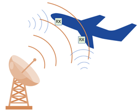
Radar receivers require low noise front ends to be able to detect targets at a long range. Simultaneously, they are frequently operated in an environment where a very high-power transmitter (a radar transmitter) will periodically leak into the receiver path, potentially damaging the receiver. A classic example of this is when a plane flies past a high-power radar transmitter, leading to damaging radiation levels for the plane’s receiver. This damage can be prevented by using a limiter.
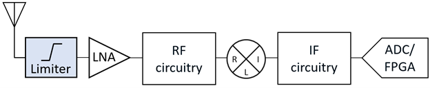
Figure 1: High power transmitters can damage high-sensitivity receiversAn ideal RF limiter is a device that passes RF signals below a certain power level and reflects signals above that power level. Performance metrics for a microwave limiter indicate how ideal an actual limiter circuit is and include:
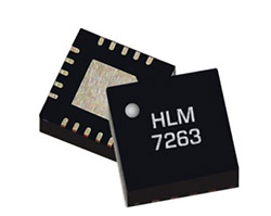
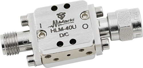
Figure 2: RF Limiters protect power-sensitive components such as LNA’s on receiver front-endsMarki’s New High Speed Broadband LimitersThrough careful design and engineering, Marki created a line of MMIC Schottky based limiters with broad frequency coverage, low insertion loss, high return loss (excellent match), high linearity, and high power handling. That makes these limiters universal building blocks for many applications. Products include: DLM-10SM– The original Marki limiter operates from DC to 10 GHz, with two channels on a single chip for easy use with differential signals. Originally designed for ADC protection, the DLM-10SM has a unique circuit design that allows the diodes to be forward or backward biased, giving a user adjustable limiting level. HLM-20PSM– Low insertion loss with high return loss from DC to 20 GHz come with high power handling in the HLM-20PSM. Power handling is 5 W CW and 50W peak using the standard 1 us 1% duty cycle pulse test, with a flat leakage of 13 to 17 dBm at 1 watt input power, depending on the frequency. It has an input IP3 value of 26 dBm at 20 GHz. HLM-40U and HLM-40CH– The HLM-40 comes in a bare die (HLM-40CH) and connectorized module (HLM-40U) package. It offers 4W of CW power handling and 20W of pulsed power handling. The design is optimized for higher frequency operation from DC to 40 GHz with an input IP3 value of 28 dBm at 20 GHz. HLM-40PSM– The HLM-40PSM combines Marki’s advanced knowledge of diode chip design and high frequency packaging to bring a surface mount limiter with low loss from DC to 40 GHz. It has a power handling of 2.5W CW and 9.5W pulsed, with a typical insertion loss value of only 0.5 dB. Input IP3 is excellent at 30 dBm at 20 GHz.
Marki Microwave HLM_40PSM Surface Mount Limiter
Marki Microwave HLM-40U Connectorized Power limiterAuthor Acknowledgement: Doug Jorgesen, PhD, is the Vice President of Engineering at Marki Microwave. He oversees the development, characterization, and applications support for cutting edge microwave components including amplifiers, mixers, and passive products. Doug joined Marki as a member of the technical staff in 2011. During a tenure of over 10 years, Doug has guided product development, technical support, marketing, and outside sales that led to topline revenue growth of over 500%. He has hired and trained more than 20 engineers to increase Marki’s technical staff by three times while introducing over 300 products and increasing the rate of product creation from 10 to over 40 annually. His application notes, tech notes, videos, and webinars on mixers, baluns, IQ mixers, and other components have been read and cited by thousands of engineers. |
 |