By Tim Daniels, Supplier Business Manager RF Power
Primary radars are strategically located in various regions to aid air traffic control (ATC) and surveillance. These radars are crucial in monitoring and managing commercial and military aircraft movements.
Terminal radar, or airport surveillance radar (ASR), is primarily used near airports and terminals. It usually operates on S or X-band frequencies and accurately covers local air traffic movements, monitoring aircraft during take-off, landing, and low-altitude flights. It helps controllers maintain separation between aircraft and guide them safely through the busy terminal airspace.
En-route radar is used for air traffic control in the airspace between airports and routes or corridors in and out of countries. It covers a larger area and is designed to handle high-altitude flights and long-distance air traffic. The lower frequency, L-band radar frequencies (1.2 to 1.4 GHz) can be used with high radiated powers to provide a longer range than terminal systems. The radars are often higher power, use a large, high-gain antenna, and are situated on elevated hilltop locations.
The UK, where I live, has a network of sixteen civil L-band primary radars for air traffic control, and one of these sites is located approximately 30 miles from my home. Titterstone Clee Hill, near Ludlow in Shropshire, in the West of the UK, is 533 meters above sea level. On its summit is a high-power L-Band primary radar.
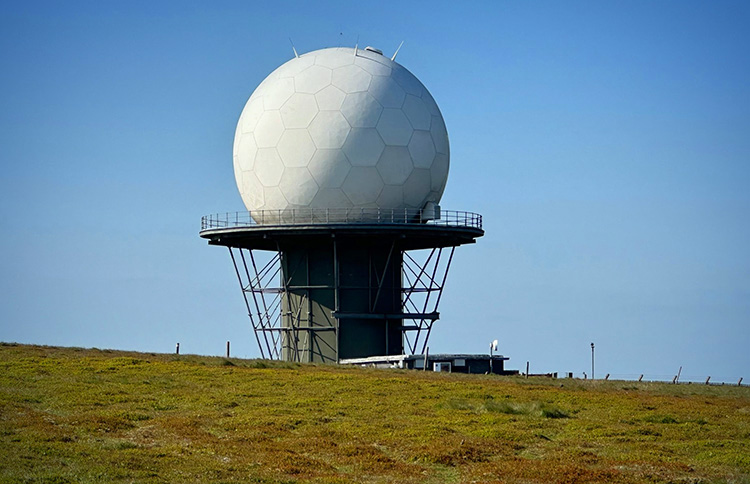
The radar is believed to be a Raytheon ASR-23SS and is run by the UK’s National Air Traffic Services. This location provides UK Air Traffic Control with radar coverage over the west of England, Wales, Ireland, the Irish Sea, and out into the Atlantic, so if you have ever flown into London’s Heathrow Airport from the US, the chances are this radar will have assisted your safe transit through UK airspace.
The Interference
For radio amateurs like me, (or radio hams as we are called in the US) living within a 100-mile range of Clee Hill and operating in the 23cm (1.3 GHz) band can present some challenges. This radar emits powerful signals, some as close as 9 MHz away from our SSB operating frequencies, where we are trying to make contacts with other amateur operators over long distances, picking out weak signals that are almost in the noise.
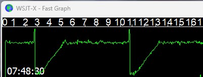
The interference I was picking up occurred at approximately 8-second intervals as the radar was rotating. I took a video clip to demonstrate the problem. Steve, (callsign G1YBB), is a strong local station, and in the clip, he is operating in a monthly contest that is held in the UK.
When there are fading, weak signals, the situation is worse. There might only be a few seconds for our information exchange, so this interference can prevent a successful contact.
Whilst the receiver’s front end suffers from Gain Compression during the pulse, the Automatic Gain Control (AGC) takes a few seconds to recover. This is visualized more easily in some software used for weak signal communications called WSJT-X.
Secondary Users
In the US and UK, radio amateurs are allocated 60 MHz of frequency spectrum between 1240 and 1300 MHz and are secondary users.
Secondary users are given a frequency allocation on the condition that they do not cause interference to other users. It also means we can claim no protection from interference from primary users.
Of course, as RF experimenters, we can at least engineer solutions to overcome some of the interference problems we encounter so I started to look for a suitable filter to attenuate the radar signals.
Assessing the Interference
When our team receives a custom filter request at RFMW, they start by asking several questions. RFMW has over twenty filter suppliers. Our team will select the correct filter topology and develop a target specification to discuss with the most suitable filter suppliers.
I first needed to understand the problem in as much detail as possible, so I started by taking some measurements of the interfering radar signals.
Measuring the Signals
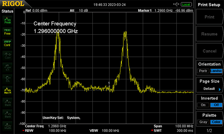
The radar signals were measured on a spectrum analyzer and found to be at 1265, 1266, 1305 and 1306 MHz. Frequency diversity in radar is known to improve detection and signal-to-noise, so it is common to see this type of radar transmission across two pairs of frequencies.
Each channel has four long pulses of 100us and four short pulses of 1us, interleaved in time across the four channels. The long pulses have an FM chirp of 1MHz bandwidth.
My receiver operates at 1296.2 MHz, so it was necessary to get significant attenuation of the channels at 1305 and 1306 MHz, which can be seen in the plot below.
The radar is more than 30 miles away, and I was surprised at how strong these signals were entering the receiver, so I decided to measure the signal strength more accurately.
Measured Power
I set the spectrum analyser to zero span with an 8-second sweep time, corresponding to the sweep time of the radar’s antenna rotation. To achieve some accuracy in measurements, it is also important to set the resolution bandwidth according to the waveform. Rhode and Schwartz has a useful application note that explains how to measure pulsed signals.
The measurement below shows my signal strength measurement. I picked the channel at 1305 MHz, which is the nearest signal and the most difficult to filter; it was measured -15 dBm, far too strong for the front end of my ICOM IC-9700 receiver which I have found has a very wide front end!
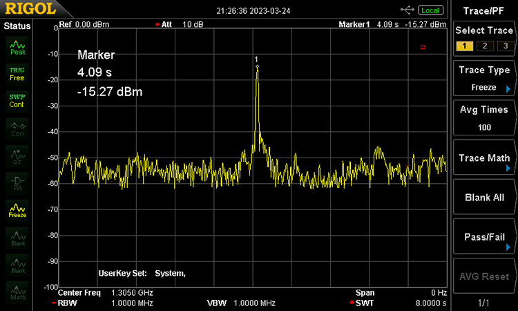
You might also notice the additional bumps in the trace either side of the main signal. As the radar rotates 360 degrees, we see the side lobes of the antenna.
Path Profile
With such strong signals, I ran a path profile between my house and the Clee Hill radar site. The Solwise website has a handy tool for a basic path profile.
The path between Clee Hill radar and my house was a line of sight, which helped to explain why the signal was so strong.
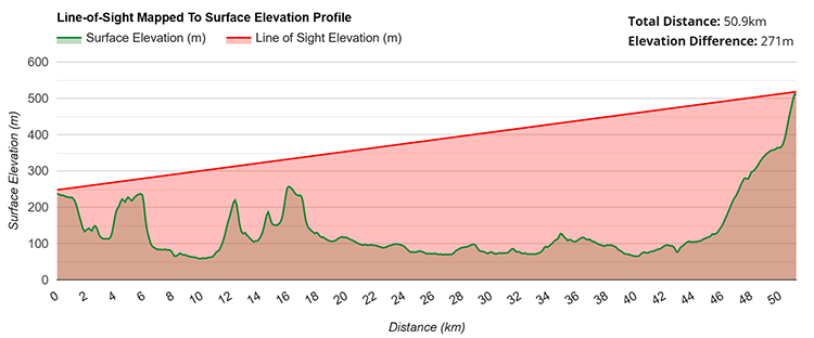
After discussing the radar interference on the UK Microwave Group discussions board, I learned it has a maximum licensed Effective Radiated Power (ERP) of +82 dBW, which is a huge 158 MW. No wonder the signal is strong at my receiver.
Calculated Power
We can calculate the free space path loss accurately when there is a line-of-sight path and we are far enough away from the transmitter.
The free space path loss is:
Lp(dB) = 20 Log(d) + 20 Log (f) + 32.5
where
Lp: path loss
d: distance (KM) = 51
f: frequency (MHz) = 1305
This gives a path loss of approximately 129 dB for the 51 km path.
So, working back from the received signal strength, we can use this equation:
ERP = Sr + Cl – Gr – Lp
where
ERP: Radiated power from radar
Sr: Signal power at the receiver (dBm) = -15
Cl: Cable losses (dB) = -1.5
Gr: Estimated receiver antenna gain (dBi) = 10
This gives 75.5 dBW as the radiated power.
The difference to the published +82 dBW could be for a combination of reasons such as:
- Measurement accuracy of the pulse on my spectrum analyzer.
- My estimation of receiver antenna gain at this frequency.
- Being below the main beam of the radar.
- Ground clutter.
- Ground reflections.
- Or maybe the radar is not transmitting at the full licensed power.
I think the most significant influence is likely my lower position, underneath the main lobe of the antenna.
How Out-of-Band Signals Can Cause Receiver Interference
Strong out-of-band signals like these radar signals can lead to interference problems in the front end of a receiver, especially these days where software-defined radios (SDR) have broad bandwidths and radios are designed to cover multiple frequency bands.
Clearly, the receiver’s front end is wider than the wanted band and no filter is perfect, and there are compromises and trade-offs to make that we often discuss with customers.
For example, compact filters with a steep roll-off and out-of-band attenuation often have a large insertion loss which is undesirable in front of the first amplification stage, usually a Low Noise Amplifier (LNA). Any loss before the LNA is added to the system noise figure.
In a low-loss front end requiring a low noise figure, we usually select a low-loss filter with just enough out-of-band attenuation for the application. When supplying an LNA from one of our suppliers, such as Qorvo or Guerilla RF, we then look for a high input IP3 that will ensure the front end is working in its linear range and won’t saturate with strong signals.
After the LNA, we can accept a filter with a higher insertion loss and more out-of-band attenuation.
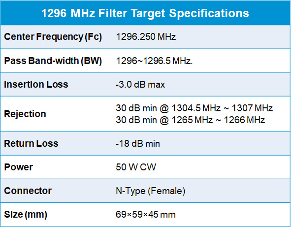
Target Filter Specification
Having defined the filter’s target specification with one of our filter experts, we decided a 5-pole cavity filter was required.
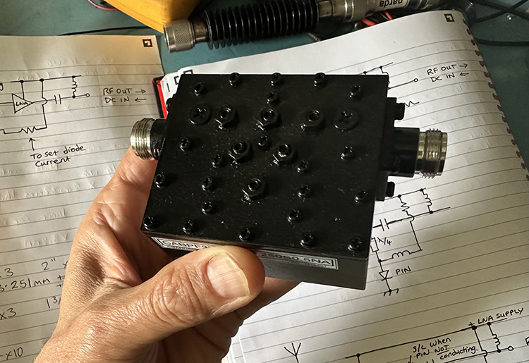
After approaching one of our suppliers, a prototype cavity filter was ordered based on the agreed target specification RFMW provided.
Six weeks later, the prototype arrived, tuned and ready to be installed.
To verify the performance, I took a plot of the filter and found it to be well within the target specification.
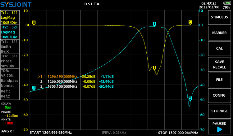
After installing the filter between the antenna and receiver, the radar signal was no longer interfering.
Whilst my job at RFMW involves working with RF power transistors and generating high-power RF for L and S-band radar, for once, I was sat on the other side of the fence!
Before I finish, I would like to thank my colleagues at RFMW, who are passionate about RF applications. Colin Field for his help with the filter specification, and Joel Levine for agreeing to supply the prototype filter for my ‘experiment’.
If you have a filter requirement, we would love to hear from you. Contact us at sales@rfmw.com.
More Technical Articles from Tim Daniels
About Tim Daniels

Tim Daniels is a Supplier Business Manager at RFMW specializing in RF Power transistor and MMIC technologies. With over 20 years of RF industry experience, Tim is a chartered engineer and holds a master’s degree in electronics innovation and a bachelor’s degree in electronics with communications. His expertise enables him to provide comprehensive design recommendations and technical support for RFMW’s customers. Tim enjoys working with engineers from around the globe to find innovative solutions to new challenges. He is a licensed UK radio amateur and, in his spare time, experiments on the VHF and Microwave bands.

